
Predictive maintenance monitoring
Wireless vibration monitoring gives maintenance teams a record of changing equipment condition. Follow pumps and conveyor drives against their own baseline, then plan the next inspection from the trend.
From site visit to ongoing review
v2-1- 01
Walk the facility with our team and show us the equipment condition you want to understand.
- 02
Select the assets and review vibration, temperature, current or process readings that can support maintenance decisions.
- 03
Agree access, gateway placement and the installation sequence around your operating schedule.
- 04
Connect the instruments and bring the agreed readings into the dashboard.
- 05
Review the baseline together, then agree alert conditions, recipients and reports.
- 06
We stay on to review readings with your team and follow what changes after adjustments or repairs.
What we install
We install vibration and temperature sensors on selected assets and bring in compatible existing condition signals. Flow monitoring can also reveal a changing process signature, as it did on Carlsberg’s transfer line.
Our wireless sensors send readings through 900 MHz radios, including Digi XBee, to a site gateway. The gateway connects those readings to your centralized dashboard.
We check instrument outputs, access and the wireless path during the site visit. Together, we agree the monitoring points, gateway connection and installation sequence around your operating schedule.
What to have ready
v2-2- Arrange access to selected assets and their proposed sensor mounting points.
- Show us a mains outlet for the gateway near the proposed installation point.
- Walk the proposed antenna positions with us so we can check the wireless path.
- Include the maintenance contact who knows the asset’s operating pattern and repair history.
- Gather existing sensor models, available outputs and the units already used for condition checks.
- Bring the operating and maintenance records you want to compare with the condition readings.
The gateway can use a separate cellular connection and buffer readings locally during an internet interruption. We agree the connection with your team.
Can we use what is already there?
v2-3We check the instrument model, enabled output and measurement unit before specifying a connection. The rows below show what to bring to that discussion.
| Output or reading | What we connect | Typical example or check |
|---|---|---|
| Vibration RMS | A selected vibration sensor or a compatible existing condition signal. | Review the unit, mounting point and the asset’s baseline. |
| Bearing or casing temperature | A suitable temperature sensor or compatible existing temperature output. | Compare the reading with the asset’s operating history. |
| Motor current | A current reading to follow motor operation over time. | Review runtime and load changes with maintenance. |
| Process flow | A compatible flow signal from the process served by the asset. | Carlsberg’s transfer-line case used flow-signature monitoring. |
Follow a changing vibration trend
The asset’s baseline gives the trend a reference. A warning-band crossing prompts maintenance to review the change and arrange an inspection.
Maintenance gets a trend to review
- Asset baseline
- Warning band
- Alarm band
What your team sees
v2-4Maintenance sees the drive-end vibration trend against the displayed alarm line and reviews the change alongside the asset’s operating history.
| Interval | Drive-end RMS (mm/s) |
|---|---|
| 0 | 2.05 |
| 1 | 2.11 |
| 2 | 2.04 |
| 3 | 2.15 |
| 4 | 2.09 |
| 5 | 2.18 |
| 6 | 2.12 |
| 7 | 2.22 |
| 8 | 2.16 |
| 9 | 2.27 |
| 10 | 2.21 |
| 11 | 2.33 |
| 12 | 2.62 |
| 13 | 2.85 |
| 14 | 3.01 |
| 15 | 3.08 |
| 16 | 3.16 |
| 17 | 3.22 |
| 18 | 3.31 |
| 19 | 3.28 |
| 20 | 3.44 |
| 21 | 3.51 |
| 22 | 3.62 |
| 23 | 3.58 |
| 24 | 3.40 |
| 25 | 3.47 |
| 26 | 3.78 |
| 27 | 3.94 |
| 28 | 4.16 |
| 29 | 4.38 |
| 30 | 4.63 |
| 31 | 4.71 |
| 32 | 4.88 |
| 33 | 5.02 |
| 34 | 5.19 |
| 35 | 5.11 |
| 36 | 5.04 |
| 37 | 4.92 |
| 38 | 4.80 |
| 39 | 4.66 |
| 40 | 4.51 |
| 41 | 4.22 |
| 42 | 3.65 |
| 43 | 3.10 |
| 44 | 2.74 |
| 45 | 2.55 |
| 46 | 2.43 |
| 47 | 2.36 |
What your team gets
You get a live dashboard with the selected condition readings and a recorded baseline for each monitored asset. Your team can review how a trend changes alongside the equipment’s operating history.
We configure alerts to phones and email around the conditions your team needs to know about. You choose the recipients, operating schedule and response to each alert.
Reports give your team a record to review alongside operating changes. Our team stays involved after installation to review the readings and adjust the monitoring as your needs change.
Who acts on an alert?
v2-5Use these examples to agree the trigger, the people to notify and the first check. Our team reviews your builder request before configuring the monitoring. Select the device and unit for your facility in the builder.
Vibration moves above its threshold
Trigger: The selected vibration reading exceeds the asset’s agreed threshold through its hold time. Notify: The maintenance lead responsible for the asset. First check: Compare the trend with the asset baseline and operating history, then arrange an inspection.
Asset temperature rises
Trigger: The monitored bearing or casing temperature exceeds the agreed condition threshold. Notify: The maintenance contact your team selects. First check: Review operating conditions and the companion vibration or current readings before inspecting the asset.
A condition sensor stops reporting
Trigger: The selected sensor stays inactive beyond the agreed interval. Notify: The monitoring contact your team chooses. First check: Check device power, batteries and the radio path.
Terms used on this page
v2-9- RMS
- Root mean square, a measure used to express the vibration signal’s overall magnitude over the measurement interval.
- Asset baseline
- The recorded behaviour used as a reference when reviewing later readings from the same asset.
- Alert threshold
- An agreed reading that brings a condition to maintenance for review, together with its timing settings.
Case studies
Carlsberg’s scheduled pump replacement followed a change in the transfer line’s flow signature. In the conveyor case, six weeks of warning means time to projected seizure. In the cavitation case, three weeks means time before audible failure.
Predictive maintenanceWaterBreweries & Beverage
A failing diaphragm pump, caught before it failed
Carlsberg Canada
A transfer line's flow signature drifted, the alert fired, and the diaphragm was replaced on a schedule instead of during a shutdown.
Scheduledreplacement
Predictive maintenanceBulk Handling & Rail LogisticsManufacturing: automotive, plastics & rubber
Conveyor-drive bearing degradation detected six weeks before failure
A bulk handling facility
The bearing’s vibration signature began changing approximately six weeks before the projected failure point.
6 weeksof warning
Predictive maintenanceMunicipal & Public Utilities
Pump cavitation caught three weeks early
A municipal water facility
The vibration signature changed about three weeks before anyone would have heard it.
3 weeksof warning
Plan the next step
- Condition sensors and gateway connections
- Build a condition alert request
Start a custom alert and choose the vibration variable for a vibration reading. Add the asset, unit and condition for our team to review.
- How alerts work
Where this fits
v2-7Conveyor drives and municipal pumps have different operating patterns. Each asset’s baseline gives maintenance a reference suited to the equipment being reviewed.
Read before the site visit
v2-8The webinar follows water readings through investigation and repair. The gateway article explains read-only monitoring and how existing equipment connects.

From monitoring to maintenance: our November webinar
Our 29 November 2023 webinar follows unexpected water use back to its cause and shows how teams use the dashboard after a repair.
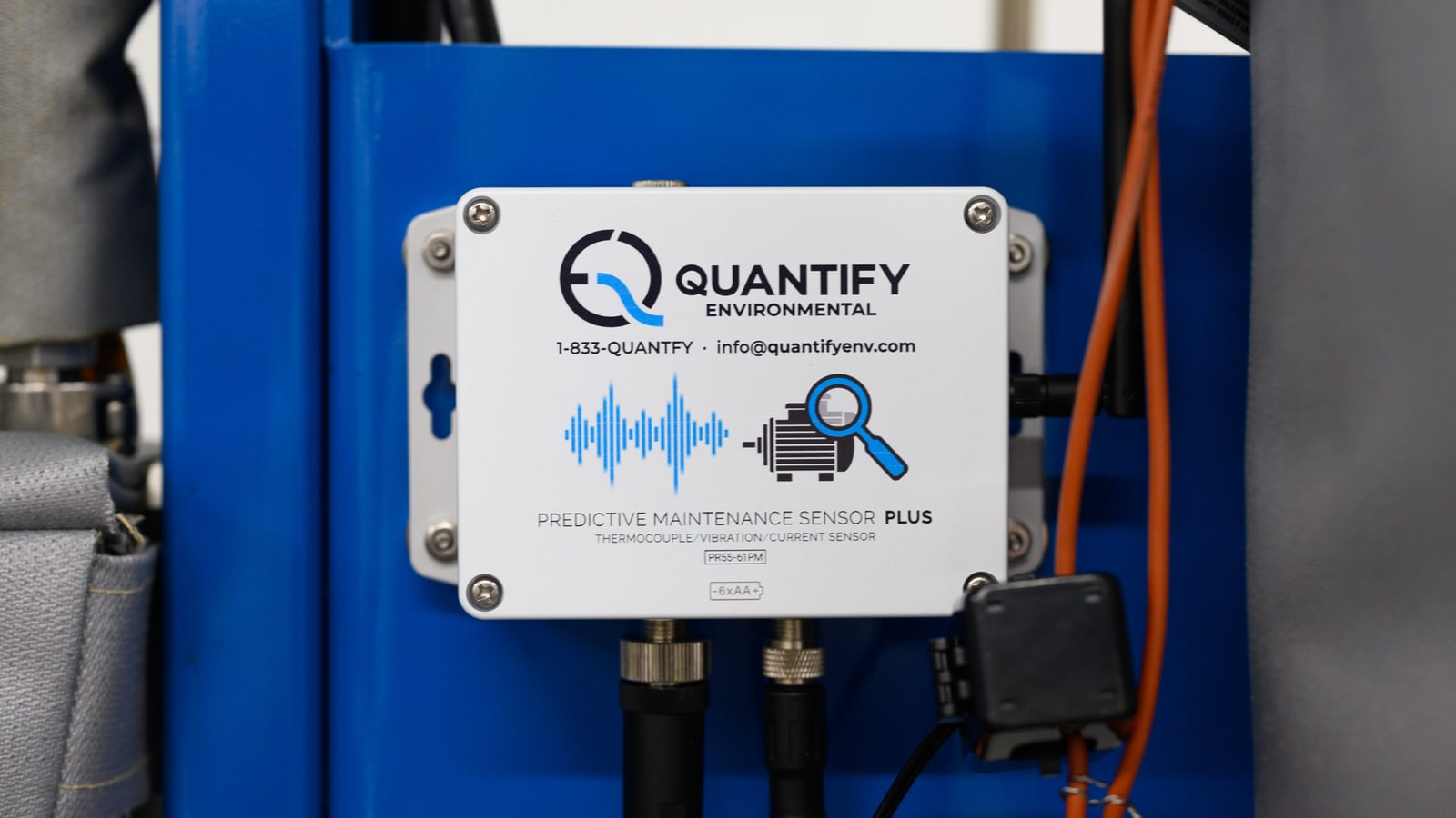
Sensor spotlight: the industrial edge computer
The edge computer collects readings from the wireless sensors at your facility and sends them to the dashboard.
Common questions
Which equipment can you monitor?
We select assets around the condition your maintenance team needs to follow. Pumps and conveyor drives are examples in the case studies on this page. Instrument choice and monitoring points depend on the asset and its operating pattern.
What changes trigger a maintenance alert?
We agree the alert condition around the asset’s recorded behaviour and the reading being monitored. Your team reviews the threshold, timing and recipients with us. A changing trend gives maintenance a reason to inspect the asset.
Can you use existing monitoring signals?
We connect compatible existing instruments alongside the sensors selected for the asset. Pulse, 4-20 mA or Modbus connections depend on the signal the device provides. We confirm the output and what it measures during the site review.
Does an alert identify the fault?
An alert identifies a condition that needs investigation. Maintenance reviews the trend and operating context, then inspects the asset to establish the cause. The readings support that decision and help the team plan the work.
What happens after an alert?
Your team reviews the trend and arranges the appropriate inspection. We stay involved in reviewing the readings and the monitoring settings. After work on the asset, the continuing record helps your team follow its return to operation.
Give maintenance a trend to act on
Walk the facility with our team and show us where equipment condition needs a clearer view. We will agree the measurements and connections to start with.
Book a site visitContact our team
or call 1-833-QUANTFY (1-833-782-6839)